|
Celso Nobre Valéria Venturini |
 |
In all of our activities, safety is one of the prime points under consideration. The same is true when we deal with industrial processes, mainly when process automation is increasingly being applied in the industries, which means that many decisions and actions, previously made by humans, are now assigned to automated equipments and systems.
 How can we be sure that safety systems will work when required? Can we trust in emergency equipment during an unexpected event?
Rules, procedures, articles and countless information and know-how were generated throughout time, making it possible to identify critical equipments during an emergency, as well as to increase their reliability and integrity when we most depend on them. When referring to block valves or safety system valves, the ideal thing would be testing them from time to time to know if they´re working properly. Generally, these valves may take long, sometimes years, before being put to work. As they are subject to weather conditions, or in aggressive and corrosive environment, normally they suffer decay inherent in the materials and concepts of the project. Will such valves work when needed?
Not very long ago, what you did was to test all valves when the process stops. They were factory breaks scheduled for equipment maintenance, new installations and process improvement. During these periods, the valves were activated, full open and closed, allowing for the following items to be checked:
- Possible stem blocking;
- Air supply leakage on the actuator;
- Tight shut sealing;
- Integrity of the valve/actuator set;
- Signal integrity on the control panel, etc.
This type of test is known as Full Stroke Test –FST.
As an industry cannot stop very often for productivity and profitability reasons, such tests might take months or even years to be carried out. In practice, if there was doubt that the valve wasn´t working properly, an emergency stop was simulated, or bypasses were applied on the normal process flow to execute the FST.
Whatever the case, high costs were required for the execution of those tests or maneuvers, both concerning the halt in the plant process and the additional equipment required for the tests. Usually the extra equipments are block valves operated manually, piping bypasses, solenoid valves, stroke control mechanical devices, not to mention logistics and the staff involved in the activity, in addition to possible company profit losses.
It would be great if such tests could be scheduled and implemented more frequently. It would be great to have parameters for evaluating the valve wear down, and allowing preventive maintenance before an emergency occurs. It would be great if the costs involved were lower.
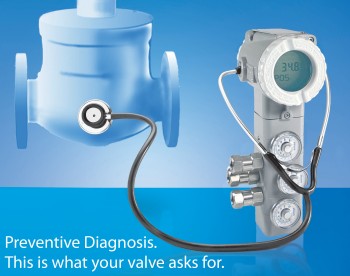
The simpler, less expensive and more reliable solution is to adopt the PST, or Partial Stroke Test. PST simply means moving partially the valve shaft and measuring the actions needed to do it. Also, it is possible to measure the valve response time, or even checking if the valve is not blocked up, or if the pneumatic actuator is correctly pressurized, without needing on-site inspection.
According to the Offshore Installations Data Manual published by OREDA (Offshore Reliability Data), the PST can detect 70% of valve problems that statistically occur more frequently. Although, in order to inspect properly a valve leakage when it is tight shut, the Total Course Test must be performed.
How long should the partial course be? This will depend on the process, so that the partial course do not interfere with the normal plant work or, alternatively, do not cause even minor oscillations on the process. In many cases, 15 percent of variations on the valve opening already make it possible to identify potential problems.
However, the automatic PST at reasonable costs was only viable after the Valve Intelligent Positioner was developed, in addition to the long list of parameters available, which, when monitored and configured, generate a wide variety of diagnostics.
SMAR newest family of Intelligent Valve Positioners, the FY400, already incorporates PST as factory default, without additional costs, with the PST commands available to be configured by the user.
Furthermore, the FY400 was developed in EDDL (Electronic Device Description Language) and complies with the FDT Group (Field Device Tool) standards. The drivers known as DTMs (Device Type Managers), designed for configuration and visualization of computerized stations with the FDT application, are described on the SMAR internet page (https://www.smar.com.br/en) for free user download.
As a consequence of the excellent PST results on the FY400, SMAR has just expanded this skillful device for the FY303 Intelligent Valve Positioner with the Profibus protocol. At no extra cost. And, similarly to the FY400, it developed the DTMs for the FY303, also available at zero cost on the SMAR internet page.
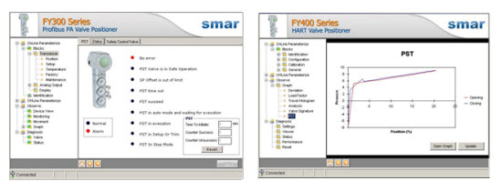
Below find a few examples of DTM screens that illustrate some PST features incorporated to the FY303.

Examples of DTM screens on the FY303
On the DTM screens it is possible to configure not only the partial course value, but also the periodicity of its automatic execution, without the interference by the operator or the instrumentation technician. The PST of the SMAR Intelligent Valve Positioner can be executed in intervals from 4 minutes up to 1 year (8760 h).
In addition, the PST can be performed with the SMAR asset management application, the AssetView. The produced data may be easily visualized on the different AssetView presentation and monitoring screens.
The method used by the FY303 and FY400 Intelligent Valve Positioners to perform the PST is called the Dynamic Ramp method. The positioner generates automatically a ramp variation of the setpoint signal on the user-determined offset range. The valve moves in response to the setpoint while the positioner reads the valve position through the position sensor, based on the Hall Effect sensor, without mechanical contact. At the same time, the positioner measures the applied pressure needed for moving the valve stem. After reaching the maximum set point, the positioner reverts for the valve to return to its original position. In the same way, during the reversion, the positioner measures the valve position and the respective activation pressure. When the test ends, the FY calculates and enables the valve load factor, i.e., the pressure value required to move the stem. And also, the related graph showing the test result.
The following figures exemplify the PST result on the FY303 and the FY400, according to the FDT/DTM protocol. Similar screens are available also on the SMAR AssetView.

PST Result Screens
When considering the growing interest in Safety Instrumented Systems – SIS, it may be said that the PST is well established and influences the calculations related to the PFD – Probability of Failure on Demand, whose rate is used in determining the Safety Integrity Level (SIL). The future will tell how these values will influence the reduction of insurance company costs to cover eventual accidents.
References:
SMAR - FY303 Instruction Manual
SMAR - FY400 Instruction Manual
Cassiolato, César Profibus training Handbook – 2008/2009
Summers, Angela – Partial-Stroke Testing of Block Valves – Control Engineering Nov. 2000
OREDA – Offshore Reliability Data Handbook – 4th Edition
