|
 |
Introduction
Safety Instrumented System (SIS) are responsible for the plant operational safety and guarantee emergency stoppages within limits considered safe, whenever the operation exceeds these limits. The principal goal is to avoid accidents inside and outside the facilities, like fires, explosions, damage to the equipment, and, mainly, prevent risks to life or damage to personal health, catastrophic impact on the community, facilitate the protection to employees and citizens, as well as to production and property.
No system is totally immune to failure and must always provide safe conditions, when a failure occurs.
Following are details involving concepts related to reliability, failures and safety, as well as the LD400-SIS, a TÜV-certified pressure transmitter for safety applications.
Reliability
The reliability of measuring systems may be defined as the median time between failures occurring in the system. In this context, failure means the occurrence of an unexpected situation that causes an incorrect output value.
Principles of Reliability
A measuring system reliability is defined as the ability to execute its function within limits and operational conditions during a given time. Unfortunately, many factors such as manufacturer tolerances to comply with the operational conditions sometimes hamper this determination and, in practical terms, reliability can only be expressed statistically through the probability of the failures that occur within a given period of time.
In practice it is very hard to determine what a failure is. When the output system is incorrect it is difficult to interpret it in comparison to the total loss of the measured output.
Quantification of Reliability in quasi-absolute terms
As shown above, reliability is an essentially probabilistic concept that can be quantified in quasi-absolute terms by the median time between failures (MTBF) and median time to fail (MTTF). Notice that both these times are usually the median values calculated by identical devices and, therefore, the values of any particular device can be different from the median.
The MTBF is a parameter that expresses the median time between failures that occur in a device, calculated in a given period of time. In cases of highly reliable equipment, to count the number of failures will be difficult and imprecise to the MTBF, and the manufacturer value is recommended.
The MTTF is an alternative way to quantify the reliability. It is normally used for thermo-couples, as they are eliminated when failing. The MTTF expresses the median time before the failure occurs and is calculated in an identical number of devices.
The final reliability associated in terms of importance to the measuring system is expressed by the median time to repair (MTTR), i.e., the mean time to repair a device or still the mean time to replace the equipment.
The combination of MTBF and MTTR show the availability:
Availability = MTBF/(MTBF+MTTR)
The Availability measures the time proportion in which the device works without failures.
The objective of measuring systems is to maximize the MTBF and minimize the MTTR and, consequently, maximize the Availability.
Failure Models
The model of a failure in a device can change throughout its life cycle and can remain unchanged, decrease or even increase.
Electrical components commonly show the behavior seen on figure 1, also known as “bathtub curve”.
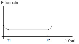
Figure 1 – Typical curve of the reliability variation of an electronic component.
Manufacturers generally conduct burn-in tests to eliminate the phase up to T1 until the products are introduced in the market.
On the other hand, the mechanic components will reach a bigger failure rate at the end of its life cycle, as shown on Figure 2.

Figure 2 - Typical reliability variation curve of a mechanical component
In practice, when the systems are electronic and mechanical compositions the failure models are complex. The more the components, the more the occurrence and probability of failures.
Laws of reliability
In practice there are several components and the measuring system is complex, and there may be serial or parallel components.
The reliability of components in series must take into account the probability of individual failures in a given period. For a measuring system with n serial components, the reliability Rs is the product of the individual reliabilities: Rs = R1xR2...Rn.
Suppose there is a measuring system made up by a sensor, a conversion element and a signal processing circuit, whose reliabilities are 0.9, 0.95 e 0.099. In this case, the system reliability will be 0.9x0.95x0.009 = 0.85.
The reliability may increase with components set in parallel, which means that the system will fail if all components fail. In this case, the reliability Rs is given by:
Rs = 1 – Fs, where Fs is the system non reliability. The non reliability is Fs = F1xF2...F3.
For example, a safe measuring system has three identical devices in parallel. The reliability of each one is 0.95 and the system reliability is given by:
Rs = 1 –[ (1-0.95)x(1-0.95)x(1-0.95)] = 0.999875
Improving the reliability of a measuring system
In practical terms, the aim is to minimize the occurrence of failures. An important aspect is to assure that the situation is identified and dealt with before time T2, when the statistical frequency of failures increases (see figures 1 and 2). The best thing is to equal T (time period or life cycle) to T2 and maximize the non-failure period.
There are several ways of increasing the reliability of a measuring system:
- Choice of the devices: always pay attention to the specified devices, their influence on the process, materials, the environment, etc.
- Protection of the devices: take adequate measures to protect the devices to improve and ensure better level of reliability. For example, thermocouples must avoid unfavorable operational conditions.
- Regularly scheduled calibration: most failures may be due to drifts that cause incorrect outputs. Therefore, in compliance to good instrumentation practices, check and calibrate periodically the equipment.
- Redundancy: when more than one equipment work in parallel and switched, sometimes automatically, reliability is significantly improved.
Safety and Reliability Systems
Safety Systems are used to monitor the status of a plant values and parameters within operational limits, and under hazardous conditions they generate alarms and put the factory in a safe state or even in the shutdown condition.
Note that safety conditions must be followed and adopted by plants whose best operational and installation practices are employers and employees duties. It is worth mentioning that the first concept regarding safety regulations is to guarantee that all systems be installed and operated in a safe way, the second being that devices and alarms involved with safety be operated with reliability and efficiency.
Safety Instrumented Systems (SIS) are responsible for the operational safety and guarantee emergency stops within limits considered as safe whenever the operation exceeds these limits. The main goal is to avoid accidents inside and outside the plant facilities, such as fires, explosions, damage to equipment, protection to production and the property and, most of all, avoid lives risks or catastrophic community damages. Bear in mind that no system is totally immune to failures and should provide a safe condition under any circumstances.
During many years the safety systems were designed in compliance with the German V VDE 0801 and DIN V 19250 standards. They were well accepted by the world safety community and lead to the current world standard, the IEC 61508, which is today the official model for operational safety involving electric and electronic systems, and programmable devices for any industrial activity. This standard covers all electro-mechanic safety systems.
The products certified according to the IEC 61508 must deal basically with 3 types of failures:
- hardware random failures
- systemic failures
- common cause failures
The IEC 61508 is divided in 7 parts, whose first 4 are mandatory and the remaining 3 are for orientation:
- Part 1: General requirements
- Part 2: Requirements for E/E/PE safety-related systems
- Part 3: Software requirements
- Part 4: Definitions and abbreviations
- Part 5: Examples of methods for the determination of safety integrity levels
- Part 6: Guidelines on the application of IEC 61508-2 and IEC 61508-3
- Part 7: Overview of techniques and measures
This standard deals systematically with all the activities of a SIS life cycle and the performance required from the system, i.e., once the SIL level signal (safety integrity level) is reached, the level of redundancy and the test interval are at the discretion of the system programmer.
In practice, the analysis and the determination of risks and SIL level must comply with the standard and the detailed analysis of the control and safety circuits. This should be carried out by dedicated professional who are familiar with the subject, especially the process and the application. What may be “tolerable” depends on the consequence of occurrence of failures. What is acceptable, compliant to the standards was defined according to the safety integrity level, SIL (See Table 1).
The IEC 61508 seeks to potentialize the improvement of the Programable Electronic Safety – PES, which includes PLCs, micro-processed systems, distributed control systems, sensor and intelligent actuators, etc.) in order to standardize the involved concepts.
Recently, several standards have been elaborated concerning SIS development, project and maintenance, which include the IEC 61508 (for industries in general), in addition to the IEC 61511, specifically for the continuous process, liquid and gases industries.
Many current applications specify SIL-certified equipment for control systems that do not need safety functions. There is also a great deal of misinformation in the market that leads to the acquisition of high cost equipment developed for safety functions when in practice they are for process control and the SIL certification does not apply and may hamper the equipment work.
Furthermore, this misinformation leads users to believe that they have a certified safety control system, when they really have a controller with certified safety functions.
In this paper, we will examine the basic differences that will clarify these specifications and help better understand them.
Instrumented Control System
Instrumented Control System is an electric, electronic or programmable system that may execute some or all of the following functions:
- Monitoring, recording or logging the plant status and the process parameters;
- Provide information to the operator about the plant status and process parameters;
- Provide alterations that may affect the plant status;
- Control of the automatic or the batch/sequential process during the startup, normal operation, shutdown and disturbances, i.e., the control within the operational limits;
- Hazard detection (namely, control with safe operational limits);
- Prevent manual or automatic actions that could start some dangerous result.
These functions are normally provided by alarms, protectors (trip, interlock, emergency shutdown) and process control systems. They may be individual or interconnected, share man-machine interfaces (indicators, display panels, graphic terminals, sound alarms etc.), plant interfaces (sensors and actuators), logic (relays, controllers, supervisory), utilities (power source, air systems) and managing systems.
The control system works as a control and not a safety tool. In these conditions, the field equipment does not need to be specified for a safety function and so, why pay more, for example, for a pressure transmitter with SIL 2 certification to be used in process control and not in a safety function? A safety function is a very simple thing. If the process temperature is too high, just open the drain valve. This is much more simple than a control function, where, if the temperature reaches 20ºC and 25ºC, opens 35% of the valve. What, if a failure occurs in the control function? It is hard to say. But the safety function is simple: just open the drain valve.
A safety equipment must be independent from the control system.
Safety Instrumented System (SIS)
As demonstrated, Safety Instrumented Systems (SIS) are credited for the operational safety and ensure emergency shutoffs within safe limits whenever the operation exceeds them.
The adequate work of a SIS calls for conditions of performance and diagnostics superior to those of conventional systems. The safe operation of a SIS includes sensors, logic programmers, processors and final elements designed to execute a shutoff whenever safe limits are surpassed. Examples are process variables such as pressure and temperature above very high alarm levels, or even to prevent unfavorable operation conditions.
Typical examples of safety systems are:
- Emergency Shutdown System (ESD)
- Safety Shutdown System (SSD)
- Safety Interlocking System
- Fire and Gas System
The Risk Concept and how to determine and check the safety integrity level (SIL)
The more the risks in a system, the harder it will be to meet the requirements of a safe system. Basically, risk is the sum of the probability of something undesirable occurring with the right consequence of the fact.
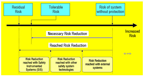
Figure 3 – Risk considerations compliant to IEC 61508
Safety systems aim at minimizing risks in acceptable levels; the SIL level for a control loop may be found by the analysis and identification of the process risks. The SIL level may be checked by the probability of failure under demand (PFD).
The IEC 61508 defines the requirements for a system functionality and integrity. The functionality requirements are based on the process, while the integrity requirements encompass reliability, one that is defined as Safety Integrity Level (SIL). There are 4 discrete levels and they have 3 important properties:
- Applicable to the entire safety function;
- As higher the SIL level, the more strict the requirements.
- Applicable to technical and non-technical requirements.

Table 1 – SIL levels
How to interpret the SIL level? As shown earlier, the SIL level is the measure of a SIL integrity, basically interpreted in two ways:
- Taking into consideration the risk reduction and Table 1:
- SIL1: risk reduction >= 10 and <=100
- SIL2: risk reduction >= 100 and <=1000
- SIL3: risk reduction >= 10000 and <=10000
- SIL4: risk reduction >= 10000and <=100000
By interpreting Table 2, where SIL 1 means that the risk of accident or something undesirable are low, and that a SIS has 90% of availability, or still, 10% of chance of failure.
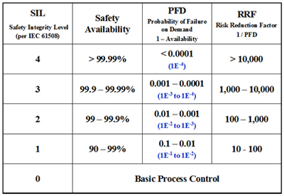
Table 2 – SIL and SFF levels according to their tolerance to a hardware failure
SIL evaluation has increased lately, mainly in chemical and petrochemical applications, and its need in relation to the probable impact on the plant and the community has even been expressed:
"3" – Protection of employees and the community.
"2" – Protection of production and the property. Possible damage to employees.
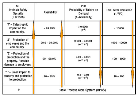
Figure 4 – SIL in function of the probable impact on the plant and the community
This analysis is not complete since it is difficult to define what is a small and a big impact.
There are many methods to identify risks:
- HAZOP technique (Hazard and Operability Study): identify risks and where are necessary higher SIL levels;
- Check List technique;
- FMEA technique (Failure Modes and their Effects), analyzes the failure on each equipment and component on the control loop.
In terms of SIL, the higher is the level required, the bigger will be the cost, due to the more complex and strict hardware and software specifications. Normally, the choice of the SIL for each safety function is determined by the experience of the professionals involved. However, the option could be the HAZOP matrix or still the Analysis of Layers of Protection (LOP), which includes the policy, the procedures, the safety strategies and the instrumentation.
In terms of comparing the SIL level reached to what was projected, the Markov Model stands out among the several methods, in addition to the failures and repair rates of the many loop elements.
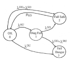
Figure 5 – Markov Model for a non-redundant 1001D subsystem
On table 2 there is the concept of Probability of Failure by Demand (PFD), where the risk of occurring something undesirable depends on the PFD and the frequency of demand. Hence, we may choose the best equipment according to the PFD through the application whose risks are clearly defined.
PFD = 1 – D, where D is the availability.
PFD is the probability of a failure occurring on a failure-preventing system. The SIL level is related to this probability of failure by demand and the risk-reducing factor, i.e., how much must be protected to guarantee an acceptable risk if a failure occurs.
PFD is the adequate indicator of reliability for safety systems.
If it is not tested, the probability of failure tends to be 1.0 with time. Periodic tests keep the probability of failure within desirable limits.
Figure 6 shows common examples of architecture for safety systems, whose techniques are used according to the desirable voting system and SIL:
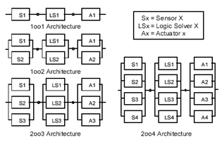
Figure 6 – Typical architecture examples for safety systems
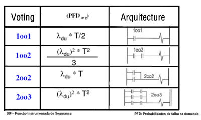
Figure 7 – Voting, PFD and Arquitecture
Some terms and concepts involved in safety systems
- Demand : every condition or event that creates the need for a safety system.
- PFD (Probability of Failure on Demand): the adequate indicator of reliability for safety systems.
- MTBF: a basic measure of reliability on the reparable items of an equipment, which may be expressed in hours or years. Commonly used in the analysis of system reliability and sustainability.
- MTBF: may be calculated by the following formula:
MTBF = MTTR + MTTF
Where:
- MTTR = Median Repair Time
- MTTF = Median Failure Time = the reverse of the total sum of all failure rates
- SFF = Safe Failure Fraction, the fraction of all failure rates of an equipment that results in a safe failure or non-safe failure, but one that has been diagnosed as such.

- Types of failures analyzed in a FMDEA (Failure Modes, Effects, and Diagnostic Analysis):
- Dangerous Detected (DD): detectable failure that may cause an error greater than 2% on the output.
- Dangerous Undetected (DU): detectable failure that may cause an error greater than 2% on the output.
- Safe Detected (SD): detectable failure that does not affect the variable measured, but moves the output current to a safe value and reports the fact to the user.
- Safe Undetected (SU): Even with a possible unknown problem with the equipment, the output works successfully within the safety 2% tolerance limit. If this tolerance is used as project parameter, this type of failure is neglectable.
- Diagnostic Annunciation Failure (AU): a failure without immediate impact, but if occurring a second time may damage the equipment
LD400-HART-SIS - Pressure Transmitter for SIL applications
The LD400 HART – SIS is a Smart Pressure Transmitter used to measure differential, absolute, gauge pressure, level and flow applications. The LD400-SIS 4 to 20 mA output signal corresponds to the applied pressure. This information is transmitted to a PLC and may be seen on the LCD display or monitored remotely via HART communication. The LD400-SIS is TÜV-certified for safety applications.
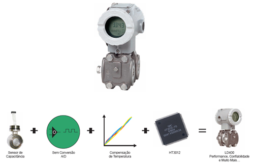
Figure 8 – LD400-SIS – Pressure Transmitter for safety applications
The LD400-SIS provides diagnostic in several levels for fast and safe maintenance:
- Sensor Level;
- Electronic Level;
- Loop Integrity Level
The LD400 performs advanced diagnostic from the moment the transmitter is turned on. For proper work, the integrity of several important figures such as characterization data, client data, calibration data and REM memory.
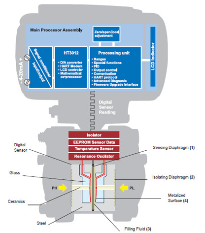
Figure 9 – LD400-SIS – Totally Digital Reading, Advanced Diagnostic and TÜV Certificate
During the operation, the validation of the measure pressure is continuously checked. Using advanced algorithms, the transmitter can identify when a failure occurs and if it is caused by a hardware defect or process overload condition. The user can configure the failure condition in compliance with the NAMUR NE43 specs. If the result of the failure causes a wrong output, the transmitter immediately changes the output current and the user can identify and fix the problem.
In addition to all diagnostics mentioned before, still there are some extra ones to reach the desired safety level. They are:
- Output Current Monitoring (4-20 mA);
- Memory and CPU Integrity Checking;
- Crystal Monitoring;
- Monitoring the Firmware Execution Sequence.
Safety Function
The LD400-SIS transmitter measures the pressure within safe precision and converts the 4 -20 mA analog output by selecting one of the available transference functions and deals with the output current in compliance with the NAMUR NE-43 specifications. In case of sensor or circuit failure, a software or hardware auto-diagnostic is executed and the current moves to a value lower than 3.6 and higher than 21 mA, which are the safety states defined for each equipment.
In order to evaluate the behavior of the LD400-SIS failure, the following definitions on Table 3 were taken into consideration.

Table 3 –Failure Modes

Figure 10 – Alarm Level
Properties of Functional Safety
Table 4 shows Values of Functional Safety obtained for the LD400-SIS.
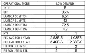
Table 4 – Functional Safety Values
The LD400-SIS provides diagnostic information through HART allowing low PDF and high SFF values.
Suppose that the LD400-SIS is failing and cannot measure the pressure within its specifications and in this situation the current loop may be harmed. The LD400-SIS has advanced diagnostics and will report through HART what is occurring and the process may be put in a safe state. The failure will become safe, characterizing the high SFF value (Safety Failure Fraction). Hence, the use of HART improves the SFF in measuring related to safety and protection.
For more LD400-SIS details, consult: https://www.smar.com.br/public/img/produtos/arquivos/ld400gsp.pdf
Conclusion
In practical terms what is sought is the reduction of failures and the resulting operational shutoffs and risks. The goal is increase the operational availability and, in terms of process, minimize variability, with direct consequence on the improvement profitability. Powerful Maintenance and Asset Management software maximize reliability and availability. An example is Smar´s AssetView, the powerful via-WEB tool that provides operational and device data and facilitates preventive and pro-active maintenance.
For more details on asset management, access: https://www.smar.com.br/en/product/assetview-online-plant-asset-management-system.
References
- IEC 61508 – Functional safety of electrical/electronic/programmable electronic safety-related systems.
- IEC 61511-1, clause 11, " Functional safety - Safety instrumented systems for the process industry sector - Part 1: Framework, definitions, system, hardware and software requirements", 2003-01
- Safety Instrumented Systems - César Cassiolato
- William M. Goble, Harry Cheddie, "Safety Instrumented Systems Verification: Practical Probabilistic Calculation"
- LD400-SIS Manual

.jpg)