
César Cassiolato
Introduction
This article shows some concepts and techniques of protection for PROFIBUS DP and PROFIBUS PA field equipments concerning high voltage signals and currents induced by lightning or other sources.
It is general knowledge that control systems installations can be constructed through the aerial and underground distribution of cables, boxes, cables near high voltage wiring that are susceptible to the exposition to lightning, electrostatic discharges and electromagnetic interference (EMI). Electromagnetic interference can be radiated (via air), conducted (via conductors), induced (normally above 30MHz) or a combination of them. The voltage generated by electrostatic discharge, taking into consideration a 50nH inductance conductors, generates voltage surges around 200V (V = L*di/dt) or more, as a current pulse produced by the electrostatic discharge has a very short upward current pulse, around 4A/ns.
This exposure may affect the behavior of signals and even damage equipment, since they have low power components that can easily burn with overvoltage.
What is a transient protector?
The transient protector is a hardware that adequately positioned and installed (as will be shown below) protects equipment by limiting the level of transients threatening them. It works almost instantaneously, “deviating” the transient to ground and controlling the voltage at a level that causes no harm to the equipment connected to it. When the current reaches an acceptable level, the normal operation is automatically reestablished.
The market offers a large variety of models. These protection devices are based on a combination of components like gas discharge tubes (GDTs, surge arresters), clamping voltage diodes, and metal oxide varistors (MOVs) characterized by fast operation, precise voltage control and automatic return as soon as the overvoltage ceases.
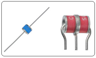
Figure 1 – Surge Arrester
Protecting PROFIBUS PA networks and equipment
In PROFIBUS PA installations the voltage that exceeds normal operation conditions are known as “surges” and appear in transitory way affecting the network behavior. It is worth noticing that, as all fieldbus networks, there is data exchange and, most importantly, ensuring data integrity and plant operational safety.
The bigger the PROFIBUS network trunk and derivatives, the bigger the transient amplitude, because of the exposure to the ground potential difference. Significant damage can also be caused to equipment connected by relatively short cables or if the circuits or components are too sensitive. In some situations, there may be serious damage to installations and equipment, depending on the energy.
The standard PROFIBUS PA network cable is the twisted pair type, precisely where the conductors twist minimize the voltage between lines. However, as mentioned before, the ground potential difference can damage the components and harm the behavior, turning the system sensitive. Also bear in mind that the cable, its distribution, are factors to be considered for minimizing noises and transients. Recommended is the use of shield, which acts like a Faraday cage and whose efficiency is maximized against common-mode noises when the shield is grounded at a signal source. In addition, it guaranteed more protection against EMI.
Conductors
Shield

Figure 2 – PROFIBUS PA twisted pair cable
Regarding transient protectors, remember that the voltage limit must not be higher than the equipment working voltage and that in practice this voltage is commonly used as twice the equipment work voltage. In terms of lightning, studies show that discharges may generate current from 2 kA to 200kA with surge currents of less than 10μs duration.
The choice of the transient protector must be careful, as it can degrade the PROFIBUS PA signal and limit the number of the equipment. Depending on the manufacturer, this device can add capacitance and resistance to the PROFIBUS PA network and both can affect the form of the communication wave signal. Moreover, some cut diodes may not be transparent for the network and can also affect the signal levels. In practice, the user must look for devices compliant with IEC 61643-21 and provide high surge currents ( around 10kA) and add less than 1? and less than 40pF to cabling.
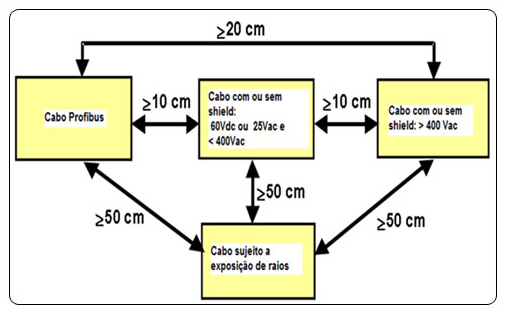
Figure 3 – PROFIBUS PA minimum recommended distances
The degree of interference on cables will depend on a series of factors such as project, construction and their features, as well as theirs interaction with other elements of the PROFIBUS network (connectors, equipment, terminals, other cables, shield, etc.), in addition to given system parameters and ambient properties. There is a variety of factors limiting the performance of digital signals associated to cables that must be considered on the project for their utilization, like:
o attenuation;
o noise, basically 4 types:
- differential noise (characteristic of the circuit);
- longitudinal noise (interference due to power supply cables);
- impulse noise;
- diaphony or crosstalk;
- distortions from propagation delay;
- jitter.
What is effective distance?
Effective distance is the physical separation between two grounded devices on the network installation. Whenever an effective distance is larger than 100m on the horizontal or 10m on the vertical between two grounded points, transient protectors are recommended on the initial and final distance points. In practice, its use is recommended on the horizontal, between 50 and 100m.
Host
Trunk length > 50m Node > 10m
Power Source
P = Transient protector
Effective distance
PROFIBUS DP Master
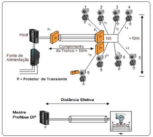
Figure 4 – Use of transient protector and effective distance
Surge Side Transient protector Protected Side PA equipment protected
Resistance in Series
Profibus PA bus Discharge device PA BUS
Shield Discharge device Shield
GND GND
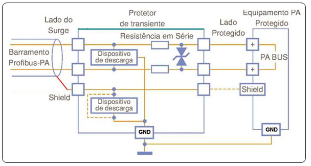
Figure 5 – Example of PROFIBUS PA transient protector
Protecting PROFIBUS DP networks and equipment
The rules for effective distance are also applicable to PROFIBUS DP network and equipment.
According to figure 6, there will be protection in case of voltage drop or when a surge will exceed the breakdown voltage or even any differential surge. As shown on figure 7, this protection is indicated when no ground is possible and so any differential surge will be converted into common mode.
Device Insulated Source Port Transient ProtectorData line
Ground line
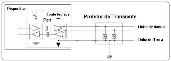
Figure 6 – Protection with ground insulation
Device Insulated Source PortTransient ProtectorData line
Ground line
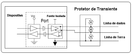
Figure 7 – Protection with common-mode insulation
In practice, the user must choose devices compliant to IEC 6143-21 and provide surge currents around 700 A.
Conclusion
This article showed concepts and techniques for the protection of PROFIBUS DP and PROFIBUS PA Field equipment related to high voltage signals and currents induced by lightning or other sources.
Whenever possible, refer to EN50170 and IEC60070-14 for physical regulations, as well as for safety practices in electric installations in explosive atmospheres.
Always act with safety in measurements, preventing contact between terminals and wiring, because high voltage may cause electric shock. Remember that each plant and system has its own safety details. It is important to be aware of them before starting to work.
To minimize the risk of potential problems related to safety, follow the local safety standards for classified areas applicable on equipment installation and operation procedures. These standards vary according to each area and are constantly updated. The user has responsibility over determining which norms to follow on his applications and make sure that every equipment is installed in compliance to them.
Inadequate installation or use of equipment in non-recommended applications may harm a system performance and the process, besides being a potential source of danger and accidents. Due to it, it is recommended that only trained and qualified personnel be used on installation, operation and maintenance.
For more details, access the direct channel for communication with SMAR engineers specialized in PROFIBUS and AS-I installation and technology on: https://www.smar.com.br/en/technical-assistance
References:
- PROFIBUS Training Material – César Cassiolato: http://www.mecatronicaatual.com.br/secoes/leitura/690, Transients Protector on PROFIBUS network, César Cassiolato
- http://www.controleinstrumentacao.com.br/arquivo/ed_139/art.html, Transients Protector on PROFIBUS network, César Cassiolato
- https://www.smar.com.br/en/technical-article/profibus-grounding-tips-shielding-noise-interference-reflections-repeaters-and-more, Grounding, Shielding, Noises and tips on installation, César Cassiolato
- http://www.profibus.org.br/news/julho2008/news.php?dentro=3, Transients Protector on PROFIBUS network, César Cassiolato
- https://www.smar.com.br/en/technical-articles-profibus
